Yang Junjun
Ankerui Electric Co., Ltd. Shanghai Jiading
0 Overview
Yinfa Investment Building is located in Debao County, Baise City, Guangxi. The construction area of ​​this project is 3360.5m2, the building area is 25686m2, of which the underground building area is 3360.5m2; the basement is one floor, the overhead layer is one floor, the ground floor is twelve floors, the total building The height is 49.8m.
In this project, a total of 15 AFRP series fire-fighting equipment power monitoring module AFPM3-2AV of Ankerui Electric Co., Ltd. was installed on the distribution box of the fire-fighting distribution circuit between the basement and the floor power station; the fire equipment power monitoring system host It is installed in the fire control general control room; the on-site power monitoring module is connected to the AFPM100/B wall-mounted fire-fighting equipment power monitoring host of the fire control room by bus. This system can alarm the fire equipment power failure in advance to prevent the fire equipment from being used normally when the fire occurs. Once the fire equipment power monitoring system is put into use, it will effectively reduce the incidence of abnormal use of fire equipment.
1 reference standard
In recent years, in order to prevent fire-fighting equipment from being used properly during the fire, the state has successively formulated or revised a number of relevant standard specifications to strengthen the monitoring of fire-fighting equipment. There are:
1.1. GB25506-2010 "General technical requirements for fire control room", in the provisions of 5.7 fire power monitors should meet the following requirements:
a) It should be able to display the working status and fault alarm information of the power supply and backup power of the fire-fighting equipment.
b) It shall be able to transmit the working status and undervoltage alarm information of the power supply and backup power of the fire-fighting equipment to the fire control room graphic display device.
1.2. GB 28184-2011 "Fire Equipment Power Monitoring System"
1.3. GB 50116-2013 "Fire Automatic Alarm System Design Specification"
2 system components
Debao Yinfa Building fire equipment power monitoring system project consists of fire equipment power monitoring background, fire equipment power detector.
The communication bus of the project is connected to a communication bus, and all the detector modules are connected to the wall-mounted background in the basement and the floor to form the aorta of the fire-fighting equipment power monitoring system. AFPM100/B fire equipment power monitoring system adopts two-layer structure networking mode of fire equipment power status monitor + voltage sensor. The whole monitoring system is comprehensive in function, safe and reliable, accurate in detection and cost-effective. The system uses RS485 network communication internally and provides Modbus-RTU communication protocol to meet the connection of other standard systems. The above-mentioned set of signals is stable and accurate. Fire equipment power monitoring system. The system networking is divided into three layers:
1) Station management
The management of the station control management system for the electrical fire monitoring system is the direct window of human-computer interaction and the uppermost part of the system. Mainly composed of system software and necessary hardware equipment, such as touch screen, UPS power supply and so on. The monitoring system software calculates, analyzes, and processes various types of data information on the site, and responds to the on-site transportation situation by means of graphics, digital display, sound, and indicator lights.
Monitoring host: used for data collection, processing, and data forwarding. Provides data interfaces for system management, maintenance, and analysis within and outside the system.
UPS: Ensure the normal power supply of the computer monitoring system, and ensure the normal operation of the station management management equipment when the whole system has power supply problems.
The background monitoring device is set in the control room.
2) Network communication layer
Communication medium: The system mainly adopts shielded twisted pair cable, realizes real-time communication between field device and host computer by RS485 interface and MODBUS communication protocol.
3) Field device layer
The field device layer is a data acquisition terminal, which is a AFPM3-2AV model fire equipment power monitoring detector.
The system structure topology is as follows:
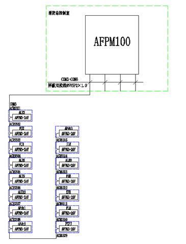
System configuration diagram PZ
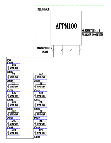
System power supply schematic
3 fire equipment power equipment
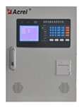
3.1, AFPM100 fire equipment power supply background:
The main technical parameters
power supply
â—Main power supply: AC220V 50Hz (allows 85%-110% range change)
â—Alternate power supply: When the main power supply is low voltage or power failure, maintain the monitoring equipment working time ≥8h
â— Monitor provides DC24V power supply for connected modules (voltage/current signal sensors)
Work system: 24-hour work system
communication method:
Modbus-RTU communication protocol, RS485 half-duplex bus mode, transmission distance of 500m (if it exceeds the transmission distance through the repeater).
Monitoring capacity ≤ 128 points
Operational rating
1 Daily duty class: real-time status monitoring, history query.
2 Monitoring operation level: real-time status monitoring, history query, remote reset of detector.
3 System management level: real-time status monitoring, history query, remote reset of detectors, remote modification of detector parameters, system parameter setting and modification of monitoring equipment, operator addition and deletion.
Environmental conditions
1 Workplace: Fire control room, or installed side by side with fire control console
2 Working environment temperature: -10 ° C ~ +55 ° C
3 Working environment relative humidity: ≤95% no condensation
4 Altitude: ≤2500m
5 Pollution degree: Class III, installation category: Level III
3.2, AFPM100 series instruments
3.2.1. Real-time monitoring of two three-phase voltages;
3.2.2, with overvoltage, undervoltage, phase loss, phase error, overcurrent (only with current detection products) alarm;
3.2.3, provide one or two channels (only monitor two-way three-phase AC voltage products) switch input function, can monitor the switch state; (see module selection for details)
3.2.4. Provide one relay output, which can be connected to the alarm control loop;
3.2.5. With event storage function, the alarm can record the time, type and parameter of the alarm occurrence. According to the alarm record, the situation can be analyzed to provide a basis for eliminating the fault;
3.2.6. Using fieldbus communication technology, the host computer management software can monitor the operation of the site at all times and timely discover the alarm information. The standard MODBUS protocol can be connected to various standard systems via the RS485 interface;
3.2.7, high integration, network, high degree of intelligence, reasonable operating characteristics;
4 system function
4.1, monitoring alarm function
â— monitored equipment power loop switch status
â—The working state of the monitored equipment power supply (voltage, current and alarm status information)
◠Alarm response time: ≤100s
â—Alarm sound signal: It can be manually eliminated. When there is an alarm signal input again, it can be started again.
â—Alarm light signal: red LED indicator is always on
4.2, control output function
â— Remote remote operation of alarm relays of individual or all monitored equipment
â— Monitor control output: normally open passive contact, capacity: AC250V 3A or DC30V 3A
4.3, fault alarm function
â— The connection between the monitor and the module (voltage/current signal sensor) is open and shorted.
◠Monitor mains undervoltage (≤80% mains voltage) or overvoltage (≥110% mains voltage)
â—The connection between the monitor and its separate power supply is open and shorted.
â— When the above fault occurs in the monitor, it can emit an acousto-optic fault alarm signal that is significantly different from the monitoring alarm signal.
◠Fault alarm response time: ≤100s
â—Fault alarm sound signal: manual elimination, when there is an alarm signal input again, it can be started again
â— Fault alarm light signal: yellow LED indicator is always on
â— During the fault, the normal operation of the non-faulty loop is not affected.
4.4, self-test function
â—Connection check: open circuit and short circuit of communication line and split power line
â— Equipment self-test: manual inspection or system self-test
◠Self-testing time: ≤60s
4.5, alarm record function
â— Record 10000 related fault alarm information
â—Alarm type: fault type, time of occurrence, fault description
â—Alarm event query
â—Alarm record printing
4.6, printing function
â— The monitoring system can print Chinese characters, and can print alarm events and time, fault events and time.
4.7, silence
In the event of an alarm such as an alarm or a fault, the speaker of the monitoring device will give a corresponding alarm sound to prompt, press the “mute†button to terminate the alarm, and the alarm light will be green. During the period, the staff can handle the faults. Everything returned to normal and the alarm light went out. If a new fault occurs, the silence indicator will turn off and the speaker will sound an alarm again.
5 Conclusion
The fire protection equipment power monitoring system of Debao Yinfa Building consists of fire equipment power monitoring device AFPM100/B and fire equipment power detector. AFPM fire equipment power monitoring system is a computer monitoring and control system independently developed by Ankerui. It can be widely used in intelligent buildings, high-rise apartments, hotels, restaurants, commercial buildings, industrial and mining enterprises, national key fire protection. Units and petrochemical, cultural and educational health, finance, telecommunications and other fields. AFPM100 fire equipment power status monitor is the core of AFPM fire equipment power monitoring system. The monitoring equipment is connected with multiple sensors through RS485 bus to form a distributed fire equipment power monitoring system to monitor the working status of fire equipment power in real time. The controller adopts centralized and modular design, and is equipped with sensors to track, collect, store and analyze the operating parameters, fault information and position information of the monitored fire equipment power supply, which is convenient for users to manage and monitor; The interactive interface displays the data of the fire equipment power supply, and has many functions such as management, viewing, alarm, and printing. The device has reasonable structure, high reliability, strong function, convenient maintenance, high cost performance, and the system interface is intuitive and easy to use.
references
[1]. Ren Zhicheng Zhou Zhong. Principles and Application Guidelines of Power Electrical Measurement Digital Instrumentation [M]. Beijing. China Electric Power Press. 2007. 4
[2]. Zhou Zhong. Application of power meter in electric energy metering of large public buildings [J]. Modern Building Electric 2010. 6
About the author: Yang Junjun, female, undergraduate. Position: Now working for Ankerui Electric Co., Ltd., contact number, mobile phone, QQ
Http://news.chinawj.com.cn Editor: (Hardware Business Network Information Center) http://news.chinawj.com.cn
Coated glass is also called Reflective Glass. It is coated on the glass surface with one or more layers of metal, alloy or metal compound film to change the optical properties of the glass to meet a specific requirement. Heat-reflective glass is generally coated on the glass surface with one or more layers of metal such as chromium, titanium, or stainless steel or a compound thereof, so that the product is rich in color, has suitable transmittance for visible light, and has higher infrared ray reflectivity, high absorption rate for ultraviolet rays, therefore, also known as solar control glass, is mainly used for architectural and glass curtain walls.
Reflective Glass Windows,Green Reflective Glass,Offline Reflective Insulating Glass,Offline Reflective Glass
Jinan Coton Glass Co., Ltd , https://www.cotonglass.com