A workshop within our company is equipped with various heat treatment systems, including Ipsen’s pusher furnace, Ai Xiulin multi-purpose furnace, circular rotary hearth furnace, and a secondary limited quenching line. These systems are responsible for the company’s heat treatment production tasks. The temperature control of the atmosphere furnace and the accuracy and stability of the carbon control system directly impact product quality. Thermocouple verification and temperature control instrument checks are handled by the company’s inspection department, while the carbon control system is verified by the workshop itself. This article outlines the procedures for completing carbon calibration according to established protocols and provides guidance on quickly addressing carbon control system failures during production.
**1. Carbon Calibration Steps and Precautions**
After the furnace has completed its atmosphere recovery, it is ready for carbon fixation. Based on our company’s process requirements, the multi-purpose furnace uses two-point carbon correction, while the continuous furnace uses single-point correction (using the multi-purpose furnace as an example).
(1) The first carbon setting target is 850°C with a carbon potential of 0.85%. Once this value is reached, the carbon potential should stabilize for about one hour. The carbon fixation method used is the "steel foil determination of carbon potential method." Our company currently uses steel foils weighing approximately 100mg and 0.02mm thick. The electronic balance model is FPG1.0, with a measurement range of 95–105mg and a precision of 0.01mg. This method is detailed in the national machinery industry standard JB/T 10312-2011.
Precautions during the process include: handling the foil carefully to avoid damage, ensuring the balance is warmed up and calibrated before use, rolling the foil into a tight cylinder and placing it at the front of the carbon rod without being too loose, checking the oxygen probe purge cycle before carbon fixation and closing the flowmeter during the process, blowing out carbon black from the fixed carbon hole using furnace pressure, and avoiding oxidation of the steel foil—redone if blue discoloration occurs.
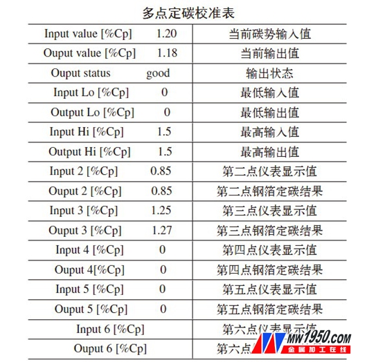
The carbon control instrument (European 2604) is then adjusted based on the carbon determination results. For example, at 850°C with a set carbon potential of 0.85%, the actual reading might be 0.9% in the Aichelin FOCOS PC program. By entering the correct values into the “Atmosphere Calculation†section, the oxygen probe’s millivolt value can be calculated. If a 4mV difference is found, the “probe offset†parameter in the “ZIRCONIA PROBE†menu is adjusted accordingly. After correction, the carbon value should match the instrument display within ±0.03%.
(2) The second carbon setting target is 920°C with a carbon potential of 1.25%. The same steps are repeated, and the instrument parameters are adjusted accordingly. For instance, if the result is 1.27%, the input is set to 1.25%, and the output is 1.27%. Multi-point calibration can be performed based on specific process needs.
**2. Examples of Carbon Control Failures**
(1) Fault Phenomenon 1: After adjusting carbon parameters, the offset becomes large shortly after rechecking. First, check for carbon deposits in the furnace. If present, the carbon control accuracy is lost, and calibration becomes ineffective. If no deposit exists and the furnace is sealed properly, proceed with troubleshooting.
Step 1: Check for carbon buildup on the probe head. Purge the oxygen probe and observe the millivolt drop. If it drops below 700–800 mV within 1 minute, the probe is clean. Otherwise, repeat purging until the value decreases. Be cautious of the probe temperature and turn off the purge gas when it reaches 960–980°C to extend the probe’s life.
Step 2: Check the reference gas flow. The flow rate should be between 6–10L/h. If bubbles are not visible in the water cup, check for leaks. Too high or low flow can affect the probe’s performance.
Step 3: Check the 2604 meter’s input module. Use a multimeter to compare the measured values with the module readings. If there's a deviation over 10mV, replace the module.
Step 4: Leak test. Turn off the reference gas for 30 seconds and check if the millivolt drop exceeds 5mV. If so, the probe may be damaged.
Step 5: Test the internal resistance of the oxygen probe. At 850°C with a stable carbon potential of 0.85%, measure the voltage across a 10kΩ resistor. If E0/Es > 6, the internal resistance is over 50kΩ, and the probe should be monitored closely.
(2) Fault Phenomenon 2: The carburizing layer is not deep enough despite normal computer monitoring. This could be due to imbalanced nitrogen-to-methanol flow ratios. If methanol flow is low, the CO content will be too low, leading to higher-than-actual carbon potential readings. Regular operator checks are essential to maintain process accuracy.
(3) Fault Phenomenon 3: Acetone solenoid valve failure causes continuous acetone injection. Even if the carbon curve appears normal, the actual carbon potential may be higher than displayed, causing defects. To fix, operators should inspect regularly and modify the system by connecting two solenoid valves in series for better reliability.
(4) Fault Phenomenon 4: The 2604 meter displays Sbr, indicating an open circuit. This happens when the probe is disconnected. Adjust the Temp Src parameter to use the back chamber temperature instead. Re-calibration is required after changing the parameter.
**3. Maintenance of the Carbon Control System**
(1) Regular carbon burning improves measurement accuracy and extends the life of the oxygen probe and equipment.
(2) Perform regular carbon calibration to ensure the system remains accurate and reliable.
(3) Replace the oxygen probe strictly according to operating procedures to prevent unnecessary damage.
(4) Operators must monitor and adjust key parameters like reference gas, purge gas, methanol, nitrogen, and acetone to maintain system performance.
(5) Equipment managers should regularly test the probe’s internal resistance and verify the accuracy of the instrument’s input modules to perform preventive maintenance.
Explosion-Proof Light
Explosion-Proof Light,Mining LED explosion-proof lights,Square LED explosion-proof light
Hanghong Lighting (Linyi) Co., Ltd. , https://www.sdhhzm.com