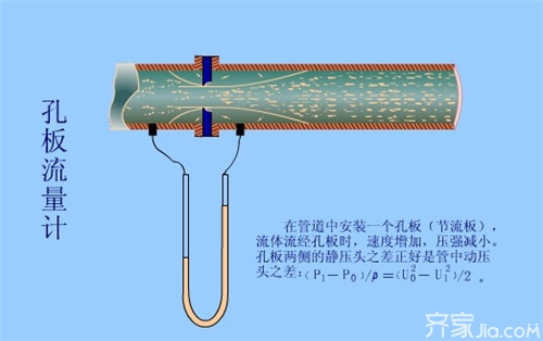
[Plate plate flow meter working principle]
The principle of the orifice plate flow meter is to measure the high-range differential pressure flow device which is composed of a standard orifice plate and a multi-parameter differential pressure transmitter (or differential pressure transmitter, temperature transmitter and pressure transmitter). The flow of gas, steam, liquid, and natural gas is widely used in process control and measurement in the fields of petroleum, chemical, metallurgy, electric power, heating, and water supply. Orifice plate flowmeter Application Scope nominal diameter: 15 mm ≤ DN ≤ 1200mm Nominal pressure: PN ≤ 10MPa Working temperature: -50 °C ≤ t ≤ 550 °C Turndown ratio: 1:10, 1:15 Accuracy 0.5, Class 1 cross-sectional area Shrinkage, so that the stable flow state is disrupted, so the flow rate will change, the speed increases, the static pressure of the gas is reduced, so the pressure drop occurs before and after the orifice plate, that is, differential pressure (where the pressure in front of the orifice section is large, through Small pressure in the orifice plate is small. There is a definite numerical relationship between the size of the differential pressure and the gas flow.
[Orifice Flowmeter Structural Features]
1, ring chamber pressure standard orifice:
Is a standard orifice. Because the ring chamber pressure is realized, the measurement accuracy is improved, and the minimum length of the straight line pipe required for installation is shortened, which can be widely applied in various departments.
2, small-caliber orifice plate:
Is a non-standard orifice. Used to measure fluids within a 10 mm to 50 mm diameter.
3, double orifice:
It consists of two standard orifice plates that are installed in a straight pipe at a certain distance from each other. In terms of flow direction, the front hole is called the auxiliary hole plate, and the rear hole plate is called the main hole plate. The section ratio m1 of the auxiliary orifice plate is greater than the section ratio m of the main orifice plate. The two orifice plates constitute a similar nozzle with a liquid wall. It is used for low Reynolds number fluid or high viscosity flow measurement.
4, round hole plate:
It is a non-standard orifice plate, suitable for the measurement of dirty, or bubbled out, or fluid flow containing solid particles with low measurement accuracy.
5, tapered inlet orifice:
Is a non-standard orifice. The angle between the circular cone and the centerline is 45°. This tapered inlet plate can be used in applications with very low Reynolds numbers, but the pipe size must not be less than 25 mm.
6, angle joints alone drilling pressure standard orifice:
Is a standard orifice. When the pipe diameter is more than 400 mm, this form is often used. The pressure can be obtained by using a separate drill hole for the flange, a pressure for the circular pressure equalizing ring or pressure for the square equalizing ring. The orifice plate may be in the form of a shanked hole or a non-standard circular orifice plate.
7, flange pressure standard orifice:

Is a standard orifice. Regardless of the diameter of the pipeline, the center of the upstream and downstream pressure-receiving holes are all located at 1 o'clock (25.5 mm) from both sides of the orifice plate. This type of refining system is generally used.
8, span pressure standard orifice:
Is a standard orifice. Pressure way for the pipeline pressure. The center of the upstream pressure tap is located at the inner diameter of the pipe in front of the orifice. The center of the downstream pressure-receiving hole is located half of the inner diameter of the tube from the rear end face of the orifice plate.
9, other.
Xiaobian epilogue: The above introduced the orifice flowmeter for everyone , and I hope to help everyone. For more relevant knowledge, please continue to pay attention to this website information platform. Follow-up will present more exciting content for everyone.
Masonry Structure Masonry Structure Refrigeration Principle Siphon Principle
Kylin Chemicals' Water Treatment Business Division is a professional Water Treatment Solution Provider offering complete control of various parameters by our highly effective chemicals and services. We have a professional team of highly qualified, trained and experienced engineers, the backup for the quality products and universal support for your water treatment needs,including the potassium monopersulfate,potassium peroxymonosulfate,reverse osmosis antiscalant. Our programs are designed to reduce our customers maintenance cost through our in-depth diagnose, knowledgeable analysis and highly effective solutions.


Water Treatment & Cleaning,Water Treatment Chemicals,Water Treatment Agent
Kylin Chemicals Co., Ltd. , http://www.kylin-chemicals.com