1 Scope
This standard specifies the technical requirements, test methods, inspection rules and signs, packaging, transportation and storage of insecticidal lamps (solar insecticidal lamps) using solar photovoltaic power generation systems as their power source.
This standard applies to insecticidal lamps powered by solar photovoltaic power generation systems. Other types of renewable energy power insecticidal lamps can be used as reference.
2 normative references
The following documents are indispensable for the application of this document. For dated references, only the dated version applies to this document. For undated references, the latest version (including all amendments) applies to this document.
GB/T 191 packaging and storage icon logo
GB/T 2423.1 Environmental testing for electric and electronic products Part 2: Test methods Test A: Low temperature
GB/T 24232 Environmental Testing for Electrical and Electronic Products Part 2: Test Methods Test I.: High Temperature
GB 4208 enclosure protection class (IP code)
GB 5080.7-1986 Equipment reliability test Verification of failure rate and mean time between failures under constant failure rate assumption
GB 7000.1-2007 Luminaire Part 1: General Requirements and Tests
GB/T 9535 Surface Crystal Silicon Photovoltaic Module Design Identification and Stereotype
GB 10396 General rules for safety signs and hazard graphics for tractors and machinery, lawn and gardening machinery for agriculture and forestry
GB/T 13306 sign
GB/T 18911 Terrestrial Thin Film PV Module Design Identification and Stereotype
GB/T 19064-2003 Technical requirements and test methods for domestic solar photovoltaic power systems
GB/T 19639.1 small valve-regulated lead-acid battery technical conditions
GB/T 20047.1 Photovoltaic (PV) Component Safety Qualification Part 1: Structure Requirements
GB/T 22473 lead-acid battery for energy storage
3 Terms and Definitions
The following terms and definitions apply to this standard.
Trap light source of trapping
Luminescent body used to trap harmful insects.
3.2
Solar PV module solar PV module
With a package and internal connection, can provide a separate direct current output, the smallest indivisible solar cell combination.
3.3
Battery battery
When charging, it converts electrical energy into chemical energy, and converts chemical energy into electrical energy during discharge.
3.4
Controller controller
The electrical equipment that controls the normal operation of the solar insecticidal lamp includes the charge and discharge control of the solar power system and the opening and closing control of the insecticidal lamp.
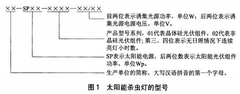
4 model representation
Solar insecticidal lamp model consists of four fields, the first part of the letter, the second part of the letter and numbers, the third part of the number, the fourth part of the figure, see Figure 1.
5 Technical Requirements
5.1 General requirements
5.1.1 Solar insecticidal lamps shall meet the requirements of this standard and shall be manufactured in accordance with drawings and process documents approved by the stipulated procedures.
5.1.2 Luminaires used on solar insecticide lamps shall comply with the relevant provisions of GB 7000.1.
5.1.3 The cast iron, stainless steel, trapping light source, lamp holder, ballast, controller and other components used in solar insect killer lamps must comply with the relevant product standard requirements, together with a quality guarantee certificate and certificate of conformity. Sampling can be carried out if necessary and can only be used after confirmation.
5.1.4 solar photovoltaic modules used by solar photovoltaic modules should meet the relevant requirements of GB/T 9535 or GB/T 18911.
5.1.5 Installation of Solar Photovoltaic Modules Solar PV modules can be installed with a fixed tilt angle to obtain maximum solar radiation energy.
5.1.6 The batteries used in solar insecticidal lamps shall comply with the relevant requirements of GB/T 22473. When selecting other types of energy storage components, their performance should also meet or exceed the relevant provisions of GB/T 22473.
5.1.7 The charge and discharge control performance of solar insect killer controller shall comply with the provisions of 6.3.2-6.3.13 of GB/T 19064-2003.
5.1.8 Solar insecticidal lamps shall have sufficient mechanical strength. All fasteners must have anti-loose measures. In site installation, sufficient foot depth must be ensured. Under the conditions of use allowed by the design, they cannot be dumped during normal use.
5.2 Appearance requirements
5.2.1 Overall Appearance Requirements of Solar Insect Killer Lamps
The size of the solar insect killer should meet the design drawings. The main frame, solar photovoltaic module bracket, high-voltage electric shock net, and collection container are all made of high-temperature resistant, cold-resistant, UV-resistant and corrosion-resistant materials. The main rod should be firm, smooth and corrosion-resistant.
5.2.2 Solar Photovoltaic Module Appearance Requirements
The solar PV module frame should be flat and free of corrosion spots, and the front surface should be clean, free from cracks and cracks, and the single solar cell must not be broken or cracked. The solar cells should be arranged neatly, and the interconnection and grid lines should be arranged neatly, without welding off, and without Fracture, there must be no continuous bubbles or delamination in the encapsulation layer. Between the battery and the bezel, the lead end should be sealed and the polarity mark is accurate and obvious.
5.2.3 Solar Power Appearance Requirements
The protective layer of the solar energy power supply enclosure should be uniform, without peeling or rust. The identification meets the requirements. Various switches are easy to operate and flexible and reliable.
5.3 Structural Requirements
5.3.1 The main part
The technical parameters of the main components of solar insecticidal lamps, solar photovoltaic modules, battery boxes, lamp shades, high-voltage electric shock nets, collection containers, etc. shall meet the design drawings.
5.3.2 Electrical Connection
The electrical connection of all parts of the solar insecticidal lamp shall be fully locked and its electrical connection prohibited the use of self-tapping darts.
5.3.3 Mechanical Strength
Each part of the solar insect killer lamp shall have sufficient mechanical strength, and its structure shall enable the insect killer lamp to not damage the electrical safety and the insecticidal function when it is normally installed and used.
5.3.4 Protection level
Solar insecticidal lamp luminaires shall have a degree of protection of at least IP65.
5.4 Solar fluorescent lamp performance requirements
The main peak wavelength emitted by the solar insect trap to trap the light source should reach 300nm-400nm or other special light bands.
5.4., Opening and closing of solar insect killer
Solar insecticidal light works automatically at night and turns off automatically during the day. Open and close automatic control methods include light control, time control, and rain control. The illuminance of auto-opening and auto-off when working in light control mode shall meet the stipulated value of the insecticidal lamp manufacturer; the error range of the time setting method shall not exceed ±30 min; when the rain control mode is working, the ambient humidity is greater than When it is equal to 98% RH, it will automatically shut off and it will automatically turn on when the ambient humidity is less than or equal to 98% RH.
5.4.2 Working hours of solar insecticidal lamps
Under normal working conditions of solar insecticidal lamps, the continuous working hours at night should be greater than 6 hours. There should be no sunshine or rainy conditions for 3 consecutive days. Solar insecticidal lamps should be able to meet the normal working hours requirements.
5.4.3 High Voltage Generator Performance
High voltage generator output voltage is not less than 4000V, high voltage discharge energy is not less than 10J.
5.4.4 Protection of solar insecticidal lamps
Solar insecticidal lamps should have short-circuit protection, over-charge protection, over-discharge protection, under-voltage protection, over-current protection, lightning protection and other protection functions.
5.5 Electrical Safety Requirements
5.5.1 Protection against electric shock
When the solar insect killer lamp is normally used or replacement components are replaced, the high voltage live parts should not be touched by human hands.
5.5.2 Internal and External Wiring of Solar Insect Killer Lamps
5.5.2.1 The internal wire of the solar insecticidal lamp shall adopt ultraviolet resistant and flame-retardant type wires, and the wires shall be arranged neatly and bound and fixed, and the wires shall not be subject to excessive mechanical stress. The cable entry shall have the necessary protection so that the cable cores are fully protected, and when the conductors are installed, their dust and water protection shall be the same as the protection level of the luminaires. External conductors should be UV-resistant flame-retardant wire.
5.5.2.2 Conductor selection for solar insecticidal lamps must meet conditions such as ampacity, voltage loss and strength requirements.
5.5.2.3 The nominal cross-sectional area of ​​internal wiring of solar insect killer lamps shall not be less than 1.5mm2.
5.5.3 Interchangeability
The vulnerable parts of solar insect light should have good interchangeability.
5.5.4 Insulation Resistance and Electrical Strength of Solar Insect Killer Lamps
a) The insulation resistance between the power output of the solar insecticidal lamp and the accessible metal parts of the insecticidal lamp shall not be less than 50MΩ;
b) The AC voltage withstand test with a frequency of 50 Hz, 1500 V and 1 min duration shall be tolerated between the power output of the solar insecticidal lamp and the accessible metal parts of the insecticidal lamp. Surface arcing and breakdown shall not occur during the test. The system shall be able to work normally after the test.
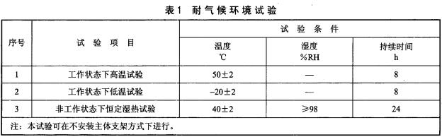
5.6 Weatherproof environment of solar insecticidal lamps
Solar insecticidal lamps should be able to withstand various tests under the climatic conditions specified in Table 1. After the test, the surface of the solar insect killer lamp should be free from damage and corrosion and should be able to work normally, and all functions should be normal.
5.7 Reliability
5.7.1 Insect Killer Parts
The life of the trapping light source should not be less than 2000h. In addition to trapping the light source and the battery system, the insect-free lamp components should have an average time of failure greater than 4000 hours.
5.7.2 Solar Photovoltaic Module
The lifetime of solar photovoltaic modules should exceed 15 years.
5.7.3 Battery
The battery life should not be less than 2 years.
6 Technical performance test
6.1 Environmental Conditions
a) Ambient temperature: 0°C to 40°C
b) Relative humidity: less than 80%.
C) Power supply: Complies with the voltage level specified in the product specification.
d) Wind speed: less than 0.5m/s.
6.2 General requirements
Inspection by visual inspection or general-purpose gage, the result should meet 5.1.
6.3 appearance requirements
Visual inspection or general-purpose gauges are used for appearance and visual inspection. The results should be consistent with 5.2.
6.4 Structure Requirements
6.4.1 Main bracket
The main support was inspected by visual inspection and general gauges.
6.4.2 Electrical connection
Check by visual and manual tests.
6.4.3 Mechanical strength
According to the test method specified in 4.13 of GB 7000.1-2007.
6.4.4 Degree of protection
According to the test method specified in 9.2 of GB 7000.1-2007.
6.5 solar insect light performance requirements
6.5.1 Turning on and off the solar insecticidal lamp
6.5.1.1 Time-controlled operation mode test, operate according to the instruction manual, set the opening and closing time, and measure with the timing device.
6.5.1.2 Light-operating mode test The illuminance of the test environment shall be measured with an illuminometer with an accuracy of not less than 1.0, and visually inspect whether the luminaire is normally turned on or off.
6.5.1.3 Rain control working mode Tests shall be carried out in an experimental environment with adjustable humidity, visually inspecting whether the lamps are normally turned on or off, or artificially simulated rainfall tests.
6.5.2 Solar insecticidal lamp working hours
Under normal working conditions, the continuous working time of the solar insecticidal lamp is measured with a timing device. The test time is 6, 18 hours or the number of continuous lighting days specified by the company. During the test, cover the solar PV modules with black cloth.
6.5.3 High Voltage Generator Performance
The high voltage generator output voltage is measured with a high voltage voltmeter with an accuracy of not less than 1.0.
6.5.4 Protection function of solar insecticidal lamp
Follow the instructions for use and check the protective functions.
6.6 Electrical Safety Performance Testing
6.6.1 Protection against electric shock
Use the test index specified in GB 4208 for testing.
6.6.2 Internal and External Wiring of Solar Insect Killer Lamps
Use a dedicated or universal gauge for measurement.
6.6.3 Interchangeability
Use standard parts for testing.
6.6.4 Insulation Resistance and Electrical Strength of Solar Insect Killer Lamps
6.6.4.1 When the power switch is turned on, between the power output terminal and the solar insect lamp can touch the metal parts. After applying a 500V DC voltage for 5s, measure the insulation resistance immediately. The insulation resistance should not be less than 50MΩ.
6.6.4.2 When the power switch is turned on, an alternating voltage with a frequency of 50Hz and 1500V is applied between the output end of the power supply and the accessible metal parts of the solar insecticidal lamp. The test time lasts for 1 min and the leakage current does not exceed 5 mA. Surface arcing and breakdown should not occur during the test. The insecticidal lamp should work normally after the test.
6.7 weather resistance testing
6.7.1 Climate under working conditions
The test sample was placed in a normal atmospheric environment for 4 hours and placed in a high temperature (low temperature) test chamber so that it was in a normal open state.
The temperature is increased (cooled) to 50 °C ± 2 °C (-20 °C ± 2 °C) at an average heating rate of not more than 1 °C/min and held for 8 hours. The test results shall meet the requirements of 5.7.
6.7.2 Climate Environment in Non-working Conditions
The test sample was placed in a normal atmospheric environment for 4 hours and placed in a hot and humid test chamber to make it in a non-operating state. The temperature was raised to 40°C±2°C at an average heating rate of not more than 1°C/min, and the humidity was 98%. RH, and maintain 24h, the test results should meet the requirements of 5.7.
6.8 Reliability Inspection
6.8.1 Test conditions
The reliability test environment should be conducted at an ambient temperature of 0°C to 40°C and a relative humidity of less than 98%.
6.8.2 Reliability Test of Solar Insect Killer Lamps
According to GB 5080.7-1986 5.6. The test time shall continue until the total test time and the total associated failure can be tested according to the specified test
When the case is accepted or rejected.
6.8.3 Reliability of Solar Photovoltaic Modules
Check the quality inspection report and factory certification of solar PV modules.
6.8.4 Battery Reliability
Check the battery quality test report and factory certificate.
7 file requirements
7.1 The manufacturer must provide user manual and system warranty certificate.
7.2 The user manual should include at least the following:
a) The working principle of the system;
b) operating procedures and precautions;
c) maintenance instructions;
d) Basic troubleshooting guidelines;
e) the size and weight of the system and system components;
f) complete list of system components, technical indicators and parameters of each component;
g) System installation instructions, functional block diagram and mechanical structure diagram.
8 inspection rules
8.1 Inspection Classification
Inspection is divided into factory inspection and type testing.
8.2 factory inspection
8.2.1 Before each product is shipped from the factory, the quality inspection department of the enterprise can pass the relevant inspection items specified in this standard and pass the inspection. Ex-factory products must be accompanied by certificates and signs.
8.2.2 factory inspection According to the provisions of 6.5 and 6.6 of this standard, the results should meet the requirements of 5.4 and 5.5.
8.3 type test
Product type tests are conducted according to Chapter 6 of this standard, and the results should meet the requirements of Chapter 5. Type testing should be performed in one of the following situations:
a) When trial production of new products is finalized and put into production;
b) When the new product or old product is transferred to the factory for test-type identification;
c) When there is a major change in product structure, process or materials used;
d) When production is resumed after the product is discontinued for one year;
e) normal batch production up to one year;
f) When the national quality management or technical supervision department puts forward the type inspection requirements;
g) When an important customer makes a request.
9 decision rules
Two sets of products are selected from the products that pass the inspection. If any of the technical specifications do not comply with the requirements of this standard, the samples are doubled, and the unqualified items are retested. If they are retested, they are qualified, if they are still not If it is qualified, it is judged as unqualified.
10 signs, packaging, transportation and storage
10.1 logo
Each product should be fixed in a conspicuous position in compliance with the permanent product label specified in GBIT 13306. The content should at least include:
a) product name, model, specification;
b) main technical parameters;
c) production company name, address, contact information;
d) the date of manufacture and the factory number;
e) product implementation standard number;
f) Other necessary safety precautions.
10.2 Packaging
10.2.1 The packaging shall comply with the relevant provisions of GB/T 191. The signs outside the box shall be clear and tidy, and include the following contents:
a) product name, model, specification;
b) production company name, address, contact information;
c) the date of manufacture;
d) "Handle with care", "Up" and other signs.
10.2.2 The following documents should accompany the box:
a) product packing list;
b) product certification;
c) product instructions;
d) Warranty card and other accessories.
10.3 Transportation
10.3.1 Packaged products should be able to withstand transport by any means of transport such as automobiles, trains, ships and airplanes.
10.3.2 In the transportation conditions and precautions, the requirements for loading, unloading and transport and the protective conditions during transportation should be stated, such as careful handling, no inversion, no pressure, no damage, etc., and should be protected from rain, snow, Dust-proof Egyptian vibration reduction measures.
10.4 Storage
The packaged product should be stored at a temperature of 10°C to 40°C, a relative humidity of no more than 80%, no corrosive gas, and a well ventilated indoor or warehouse.
Infrared range finder refers to laser infrared range finder, which is a kind of laser range finder. Infrared rangefinder is an instrument for precision ranging with modulated infrared light. The measuring distance is generally within 150 meters, and the accuracy is about 2mm. This is the most widely used laser infrared range finder. In addition to the function of measuring distance, one can also calculate the volume of the measured object. Infrared rangefinders are widely used in topographic survey, battlefield survey, tank, aircraft, ship and artillery target ranging, measurement of clouds, aircraft, missiles and artificial satellite altitude. It is an important technical equipment to improve the accuracy of high tanks, aircraft, ships and artillery. Because the price of laser infrared rangefinder is decreasing, the industry is also gradually starting to use laser infrared rangefinder, which can be widely used in industrial measurement and control, mines, ports and other fields.
infrared range finder, IR laser rangefinder, infrared distance measure, laser infrared range finder, infrared rangefinder
Chengdu ZT Electronics Technology Co., Ltd. , https://www.lasermeasuretool.com