This paper describes in detail the installation and commissioning, probe calibration and application examples of the software of the Renishaw OMP60 machining center workpiece measuring system in the horizontal machining center of the FANUC system.
1. Renishaw OMP60 machining center workpiece measuring system
The Renishaw OMP60 OMI-2 optical transmission system is a new generation of optical systems. Following the RMP60 wireless probe, Renishaw has recently introduced the OMP60, a new generation of optical probes for medium and large machining centers and turning and milling centers. The system uses the most advanced modulation optical transmission method and has strong anti-light interference capability. The OMP60 probe is also compatible with existing OMI-2 and OMI receivers, so some of its innovative features will benefit current MP7, MP8, MP9 and MP10 users. With Renishaw's proven trigger logic, multiple probe on/off options allow for performance without the need to disassemble the probe. Using a commercially available AA battery, the battery life can exceed 6 months, greatly reducing machine downtime and maintenance costs. As with previous products, the probe and interface are designed to withstand strong shocks and vibrations, greatly reducing false triggering. Based on a commitment to support existing systems, OMP60 can be used to replace the many systems that Renishaw has developed for users in the past.
2. Software installation and parameter setting
(1) Software installation Change all files whose names begin with O97 and O98 in the FAUNC system to other file names.
The installation files 40120519, 40120520, 40120521, 40120727 are all copied into the FAUNC system.
(2) Parameter setting 1 probe retraction distance and detection feed rate setting: probe retraction distance and detection feed rate need to be set according to the condition of the machine tool, macro program O9836 is opened, #506 is retracted Distance, #119 is the detection feed rate. The default value of #506 is 0.5, and the default value of #119 is 5000. 2 tool paranoid type setting:
In the macro program O9724, #120 is the tool paranoid type setting, which must be consistent with the parameter setting in the FANUC system. The matching parameter of the horizontal machining center of our factory is #120=9.
3. Probe calibration

(1) Significance of calibration The physical length error of the probe and the eccentricity of the probe on the X and Y axes and the vector radius of the ball are detected by calibration of the probe for offset compensation in future workpiece inspection.
(2) Preparation before calibration 1 The cutting sample is clamped to the horizontal machining center table, the surface of the sample is milled with a face milling cutter, and then finished milling to ensure that the surface roughness of the workpiece is greater than 1.6 μm. 2 Using a fine boring tool, the center of the cutting sample is sturdy (hole depth greater than 35 mm, hole diameter greater than 50 mm), and the inner diameter of the hole is accurately measured using an inner diameter meter and a micrometer. 3 Using the gauge block, the Z-axis workpiece coordinate system of the surface of the cutting sample is detected. 4 Install the probe on the spindle, roughly measure the length of the probe with a caliper, and fill the measured value into the corresponding tool length compensation position in the FANUC system tool table.
(3) Calibration cycle The steps of the calibration cycle are shown in Figure 1. The procedure is as follows:
%O5211
M19 (for spindle orientation)
M35 (probe open)
G0G90G54X35.Y0 (quickly move to the upper end of the sample hole for probe length calibration)
G43H1Z100 (activates the No. 1 tool offset and quickly locates 100 mm from the surface of the sample)
G65P9810Z30.F3000 (protection movement is positioned 30mm from the surface of the sample)
G65P9801Z0T1 (calibration of probe length)
G65P9810X0Y0 (protection positioning to sample center position)
G65P9810Z-5. (Protect positioning to the hole -5mm position)
G65P9802D50.001 (calibrate the probe within a 50.001 mm diameter to determine its X, Y stylus offset)
G65P9804D50.001 (Calibrate the probe in a 50.001 mm diameter bore to determine the ball diameter, including vector direction)
G65P9810Z100.F3000 (protects positioning movement, retracts to 100mm)
H00 (cancel length offset)
M36 (probe closed)
M30 (end of program)
%
(4) Data check after calibration In order to check whether the calibration is accurate after the calibration, open the macro variable in the FANUC system to view the value: #500 (XRAD) is the X-direction calibration radius, #501(YRAD) is the Y-direction calibration Radius, #502 (XOFF) is the eccentricity of the X-axis stylus, and #503 (YOFF) is the eccentricity of the Y-axis stylus.
The stylus ball radius used by our horizontal machining center is 3mm. If the values ​​of #500 and #501 are large, it indicates that there is an error in the calibration. It is necessary to re-check the detected value for calibration.
After the probe is installed, the stylus ball must be tested for beating less than 0.01mm. If the values ​​of #502 and #503 are large, the jitter detection should be performed again and then calibrated.
4. Application examples
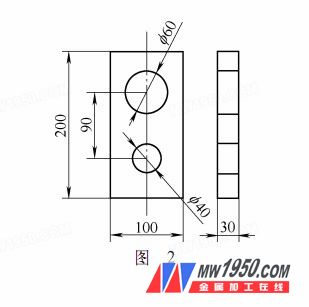
As shown in Fig. 2, the workpiece measuring system is used to establish the workpiece coordinate system of G54 with the hole on the workpiece as the center and the lower surface of the workpiece as zero. When the Z-axis zero point is detected, if the detected value is greater than the original value, the error is greater than 0.1 mm. The clip has a problem, an alarm is generated, and the detected value is saved to a separate file for later quality tracking after the test is completed. The procedure is as follows:
%O0010
T1M06 (adjust the probe to the spindle)
G90G0G54X100Y0 (fast move to start position)
M19 (for spindle orientation)
M35 (probe open)
G43H1Z100 (activates the probe length offset, quickly locates 100 mm from the fixture under test)
G65P9810Z30F3000 (protection positioning moves to the position of the fixture surface 30mm)
G65P9811Z0U0.1W1S1 [Measure Z-axis zero point (U is the upper limit of tolerance, if the over-differential cycle stops and alarms, W is to save data, S is to set the workpiece coordinate system offset number, No. 1 is workpiece coordinate system No. 54)]
G90G0G54Z100 (fast retraction to a position 100 mm from the fixture to be tested)
G90G0G54X0Y0 (fast move to start position)
G65P9810Z20W1F3000 (Protect positioning moves inside the workpiece hole to be tested)
G65P9814D60S1 (measuring the inner hole with a diameter of 60.0mm)
G65P9810Z100. (Protect positioning movement)
M36 (probe closed)
...
5 Conclusion
This paper introduces the installation and debugging, probe calibration and application examples of the software of the Renishaw OMP60 machining center workpiece measuring system in the horizontal machining center of FANUC system, which proves that the application of this system can greatly improve the machining efficiency of the horizontal machining center machine tool. Reduce production costs and reduce scrap rates.
We produce various kinds of hand-carved stone animal figurines, such as stone owl statue,carved stone elephants,carved stone bears penguin stone gift -since 1995,which are suitable for home and garden decoration,
Description of Carved Stone Animals:
Brand Name:HR stone
Product Name: stone animal statues, carved stone animals
Type: granite,white jade
Color: grey,black,yellow,white,painted color
Size :custom,for stock,please contact us for details.
Design:custom or stock
Material Origin: China
Uniquness:pure hand-carved
Application:home decoration,garden decoration,handicrafts and gifts
Packing: firstly in foam plastic ,then in strong wooden
MOQ:100pcs
Deliver port:Xiamen

Animal Sculpture,Stone Dog Statue,Stone Owl Statue,Stone Garden Owls
Fuzhou HuaRen International Imp&Exp.Co,Ltd , http://www.huarenstone.com