Zhongwang 3D's easy-to-learn and easy-to-use features can help beginners quickly master 3D CAD design. This shared headset CAD design tutorial is very suitable for beginners looking for 3D. This CAD tutorial is easy to learn, and the 3D CAD commands are quite rich. It is very helpful to consolidate the knowledge of 3D CAD. Then we will introduce the specific 3D CAD design ideas.
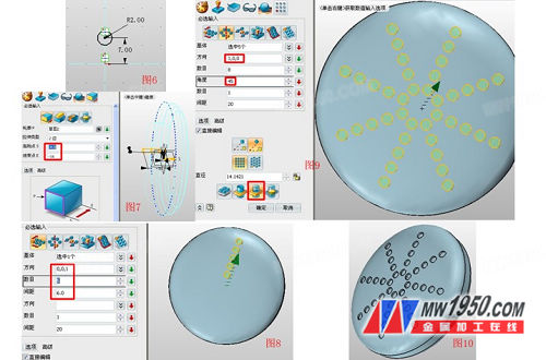
First, insert sketch 1 on the YZ plane and draw a circle with a radius of 40, as shown in Figure 1. Exit the sketch, stretch the outline of sketch 1, and perform the drafting operation. The parameters are shown in Figure 2. The stretched solid edge is rounded and the other side is dome-shaped. The parameters are shown in Figures 3 and 4. The formed dome is shelled to a thickness of -1, as shown in FIG.

Second, insert sketch 2 on the YX surface and draw a circle with a radius of 2, as shown in Figure 6. Exit the sketch and stretch the graph of sketch 2 with a starting point of -4 and an ending point of -16, as shown in Figure 7. Click Array - Linear to select the attribute filter as the shape. The base is the extruded cylinder in Figure 7. The parameters are shown in Figure 8. Click the Array tool again and select the circle option. The base is the 5 cylinders behind the array in Figure 8. The parameters are shown in Figure 9. Note the “Remove Selected Entity†below, then press OK. 10.
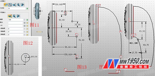
Third, insert the datum plane and offset -100, as shown in Figure 11. In this datum, insert sketch 3 and draw a circle with a radius of 10, named curve 6, and the parameters are shown in Figure 12. Insert sketch 4 on the XZ plane, select the reference geometry - reference curve, use the edge shown in Figure 13 as the reference curve, click "point", make 4 points with reference to Figure 13, draw the curve by point, and use the reference curve and 4 The points are connected, and the resulting curve is named curve 1 and hidden by the hidden function, as shown in Fig. 14. Exit the sketch, and similarly, insert the sketch 5 on the XZ plane again, and draw the curve shown in Figure 15, named curve 2.
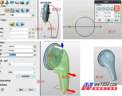
Fourth, insert the reference plane and offset, as shown in Figure 16, insert the sketch 6 on the offset surface, click the reference geometry function - the curve intersects, and the curves 1, 2 of Figure 16 are referenced to form two reference points. Click on the circle function - two points, draw a circle through two reference points, named curve 5, as shown in Figure 17, the role of this circle is "body shaping", to avoid the entity after the loft is too "obese." Click the double-track lofting function. Path 1 and path 2 are curve 1 and curve 2, respectively. The contours are the curves 4, 5, and 6 shown in Fig. 18. The effect is shown in Fig. 19.
Fifth, insert the reference plane and offset, as shown in Fig. 20, insert a sketch 7 on this reference plane, and draw a circle with a radius of 4 as shown in Fig. 21. Click the Stakeout function and the outline is the two sides shown in Figure 22. You will find that the formed surface is distorted due to the inconsistent direction of the two contours, as shown in Figure 22, red and white arrows, click Advanced Options. - Automatic - Modify, the "Line" option selects the white dashed line, and the "New Point" is selected at the point in the same direction as the red arrow shown in Figure 24, and the effect is shown in Figure 25.

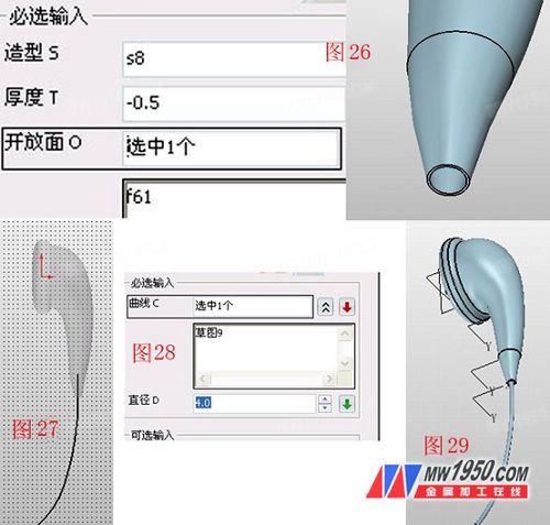
Sixth, click on the shelling function, select the curved surface of Figure 25, the thickness is -0.5, and the opening aspect is the lowermost round surface. The effect is shown in Figure 26. Insert the sketch 8 on the XZ plane, draw the curve shown in Figure 27, click the rod sweep after exiting, select the curve of the sketch 8, the radius is set to 4, the effect is shown in Figure 29.
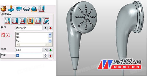
Seventh, hide the three datums, click the copy function—copy in the direction, select all entities, and move 140 in the negative direction of the X axis, as shown in Figure 30. Click on the move - rotate around the direction, select the copied entity, rotate 70 degrees around the Z axis, the parameters are shown in Figure 31, and then adjust the orientation of the entire model, adjust the color in the surface properties according to your preferences, the effect is shown in Figure 32. . At this point, the main part of the headset is complete.

Through this 3D CAD learning tutorial, you can more fully understand the 3D CAD intelligent design of Zhongwang 3D, reduce the time cost brought by CAD software operation, and pay more attention to the improvement of product CAD design itself. Interested friends may also try to use the high-efficiency CAD design of Zhongwang 3D to draw a beautiful earphone of their own!
Ferro Tungsten belongs to ferroalloy series (containing tungsten: 70%-80%), an alloy composed of tungsten and iron, used as an alloy additive for steelmaking. The commonly used tungsten iron is tungsten containing 70% and 80%.
Tungsten and iron are the main components of the iron alloy. It also contains manganese, silicon, Carbon, phosphorus, sulfur, copper, tin and other impurities, and is an alloying agent for steelmaking. According to different amounts of tungsten, the tungsten and iron are divided into: FeW75 (including W70% ~ 80%, C ≤ 0.20%, P ≤ 0.04%, S ≤ 0.08%, Si ≤ 0.5%, Mn ≤ 0.25%) and FeW80 (including W75.0%~85.0%, C≤0.20%, P≤O.04%, S≤0.08%, Si≤0.7% and Mn≤0.25%).
Ferro Tungsten
Ferro Tungsten,High Quality Ferro Tungsten,Ferro Tungsten For Pile-Up Welding
Hwa Seng Resources (Hong Kong) Co., Limited , http://www.hwaseng-resources.com