1 Introduction
With the continuous development of electronic technology, more and more large-scale programmable digital logic devices, such as FPGAs, are used in electronic devices. The use of such devices increases the performance of electronic devices and increases reliability, but at the same time complex logic relationships and fine pins also put tremendous pressure on the maintenance of the device. Maintenance personnel cannot measure the waveform on the chip pins through the probe, and the use of a dedicated test platform such as a "needle bed" requires a high cost. The birth of boundary scan technology provides a new solution to this problem. The Boundary Scan Protocol was proposed by the Joint Test Action Group (JTAG: Joint Test Action Group) and formed the IEEE 1149.1 industry standard in 1990. The standard improves the board's testability by testing the device and peripheral circuitry through a boundary-scan unit placed between the device's I/O pins and the core circuitry. Boundary scan is like a “virtual probeâ€, which can collect the status information of the chip pins without affecting the normal operation of the board, and analyze the information to achieve the fault diagnosis function. In view of the current difficult situation of complex digital circuit board rapid test, this paper designs a circuit board test system based on boundary scan, which can quickly diagnose complex digital circuit boards with boundary scan interface and help maintenance personnel to carry out maintenance.
2 Design of circuit board test system based on boundary scan
2.1 Design requirements (1) Test the circuit including the boundary scan interface. The user needs to customize the JTAG scan chain structure of the board under test according to the actual situation.
(2) It can not only collect the boundary scan link and interface signals on the circuit board, but also realize the test function of the module on the circuit board in the offline state.
(3) It can realize the function of displaying, recording and analyzing data, and presetting the system triggering and stopping conditions.
(4) Perform a quick analysis of the collected signals and generate test reports for use by maintenance personnel.
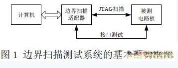
2.2 Basic structure and working principle The system consists of a computer and a boundary scan adapter. The two are connected by a parallel port of the computer. The overall block diagram is shown in Figure 1.
When testing with this boundary scan test system, the scan chain on the board should be tested first to ensure that the scan chain is normal. Then choose online functional test or offline functional test according to the actual situation. The online function test means that the circuit board does not leave the device, and the working state and fault distribution of the circuit board are judged by collecting the data of the boundary scan unit and the circuit board interface in the circuit board. This step is suitable for quick diagnosis and quick repair of the board. The off-line function test means that the circuit board is disconnected from the device. After the power is connected, the test system loads the signal on the circuit board, and the sub-module tests the entire circuit. This step is suitable for use when servicing a faulty board. If you suspect that the system itself is malfunctioning, you can diagnose it by self-test.
Turbine Flowmeter,Turbine Flow Meters,Electromagnetism Flow Meter,Turbine Wheel Flow Meter
Jingsu Huaerwei Science and Technology Group Co.,Ltd , https://www.huaerweiflewmeter.com