According to the manufacturing process analysis, the shape of the block is basically composed of four arcs. Except for the R10mm arc, it can be produced by the pre-machining of the blank. The other arcs and the 57mm cylinder are finished by milling. The parts are processed in a single piece and in small batches, and should be clamped as much as possible using a universal fixture. However, due to the shape limitation of the living block, how to complete the milling of the four arcs by correcting the center of the four arcs during the clamping process becomes the key to directly affecting the entire processing quality and the effect of the living block.
In order to ensure the relative positional accuracy of the four arcs and the 53mm through holes, the same reference should be used during processing. In order to meet the above clamping requirements, the moving block blank is lengthened, and the lengthening portion is used as a positioning standard for the clamping process in the whole processing process, and after the parts are completely processed, the lengthening portion is removed. Turning the blank before milling, for example, the arc of the block 4 is not concentric. Therefore, before milling, R10mm, that is, a cylinder of 5200105mm, with a length of 80mm, is used for turning and is used as a positioning reference for milling.
Milling process 1) Machining R3175mm arc, 53mm hole and 57mm outer circle. The center of R3175mm arc, 53mm hole and 57mm outer circle are all on the same line OO1. First fix the chuck (3 claws or 4 claws) on the vertical milling machine table, and clamp the 520mm@80mm blank on the chuck. At the same time, use the dial indicator to align the 520mm outer circle center axis with the milling machine spindle axis. The degree is within 0102mm. Move the milling machine table 015mm vertically to the right, so that the axis of the milling machine spindle is coaxial with the center of the R3175mm arc, and the hole of 57150102mm is processed and the depth is 16mm. This produces the R3175mm circular surface.
Move the milling machine table 615mm to the right and make the spindle axis of the milling machine coaxial with the 53mm hole axis. Drill the hole to 53-0102-0104mm and -0102-0104mm as the grinding allowance after the process. A 57mm@113mm outer step is machined by a special boring tool holder for milling machines. Processing 2-R8mm arc and 5mm@315mm step As shown in the figure, before processing 2-R8mm arc, first cut the shading part margin, depth 20mm, and the plane E processed at the same time as the processing of 2-R8mm arc Clip positioning reference.
When milling a 2-R8mm arc, the centers of the two R8mm arcs O3 and O4 (if) must coincide with the center of the circular table. In order to adjust the position of the O3 and O4 and the rotary table of the circular table, the eccentric chuck can be fixed on the round table. Before the milling, the eccentric chuck eccentricity is adjusted to zero, and the center of the eccentric chuck coincides with the center of the circular table. The workpiece is clamped on the eccentric chuck with the R10mm outer circular surface as the reference. At the same time, the front E is perpendicular to the horizontal movement of the milling machine. This can be adjusted by adjusting the eccentric chuck eccentricity OO3 and turning the circular table clockwise through the H angle (OO2). The angle with OO3, where OO2=OO1+O1O2=7+0154=7154, tgH=O2O3/OO2=0185/7154=01113 ie: H=6b15c), so that the center O3 coincides with the center of rotation of the circular table to achieve R8mm Milling of the arc. Then turn the round table counterclockwise through the 12b30c angle. In the same way, the R8mm arc with the center of O4 can be milled.
The eccentricity of the eccentric chuck movement during machining is: OO3=OO4=OO2+O2O23=71542+01852=71559mm After the 2-R8mm circular surface is finished, it is not necessary to remove the workpiece, and only the eccentric chuck is adjusted to zero. Rotate the round table 6b15c clockwise, complete the 5@315mm step with a T-knife, and finally cut the lengthened portion with a slitting cutter, and all the milling processes are finished. After the heat treatment process and subsequent processing of the block milling, the burr is removed, and then the surface is carburized and quenched. The depth of the carburized layer is 015017mm, and the surface hardness of the working block is controlled at HRC5058. After the heat treatment, the 53mm hole is polished to the size requirement, all Processing is over. The use of the live block after the above processing is installed in a pneumatic screwdriver, and the operation is stable, the torque is large, the noise is low, the impact motion and the forward and reverse movement are normal. After 9 months of use, it can still be used, which exceeds the use period of the original live block and achieves the ideal use effect.
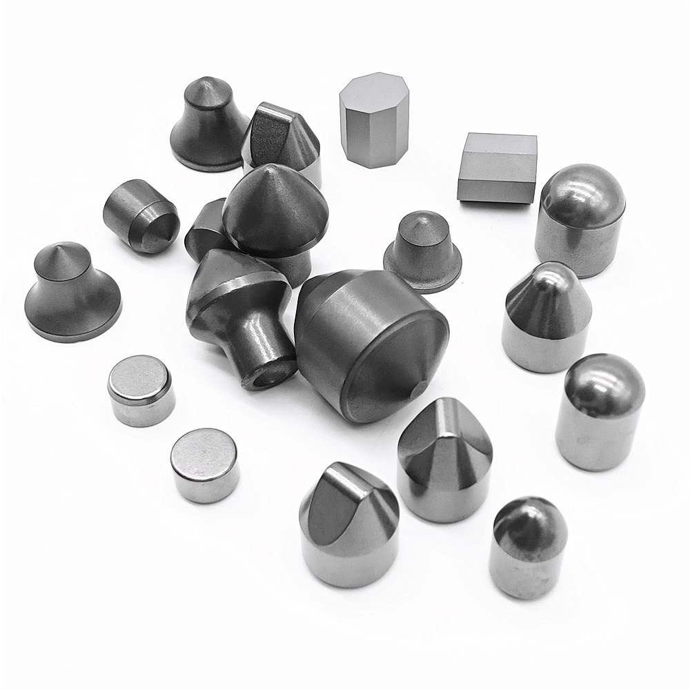
Zhuzhou Kerui produce a lot of tungsten carbide products. Carbide wedge buttons is one of our Carbide Button products, except tungsten carbide wege buttons,we also manufacture many other types of carbide buttons, for example, tungsten Carbide Spherical Button, carbide dome buttons, carbide ballistic button, cemented Carbide Parabolic Button, carbide flat-top buttons, etc. Customized carbide buttons for drill bits or custom carbide products are also available.

Carbide Wedge Button,Eccentric Carbide Button,Carbide Button For Mining,Carbide Wedge Button For Oil
Zhuzhou Kerui Cemented Carbide Co., Ltd. , https://www.carbide-china.com