After the definition of the connection condition is completed, a vertical downward gravity of 9.8N is defined. According to the output power of the motor, the rotation speed of the start-up crank shearer is 280 deg/s. According to the thickness and rotation speed of the rolling stock, the shearing process is obtained. For 0.35s, we add a shear force to the cutting edge (both cutting edges are added). In the motion simulation module of AIP11, the designer can add the mechanical curve to the part editing according to the actual needs. Here we approximate the cutting. The maximum impact force calculation in the process. The crank has a shear force after 0.15s of movement. After 0.5s, the shear force disappears and the direction of the direction of force remains vertical, so we have to choose the “fixed load direction†(see Figure 14). To capture the closed curve formed by the cutting edge motion, we also need to add a motion trajectory at the cutting edge. (See Figure 15)
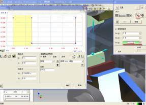
Figure 14 Adding a mechanical curve
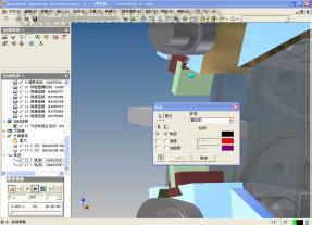
Figure 15 Loading the motion track
After all the mechanical conditions have been loaded, click on the simulation template at the bottom left to enter the motion simulation. The motion path of the flying shear is clearly displayed (see Figure 16), and the parameters of each point are output to the spreadsheet (see Figure 17). . If you need specific mechanical changes at each position, click on the “Output Grapher†in the tool panel, select the hinge point force curve you want to view, and search for the maximum value of this curve generated by the simulation (see Figure 18). The data is transferred to the finite element module analysis (it is worth noting that we need to define some relevant connection points).
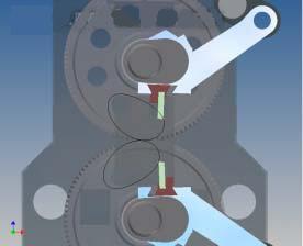
Figure 16 Closed trajectory curve generated by cutting edge motion
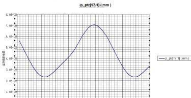
Figure 17 Closed curve output to spreadsheet
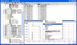
Figure 18 Searching for the maximum force point in the curve
Load the crank with the maximum stress found in the chart, and define the connection point of the crank. Double-click the crank to enter the stress analysis environment of the part. Click “Motion Load†and the software will automatically load the force condition of the part in the motion simulation. For the force analysis, since the designed crank is an asymmetrical structure, we can clearly see the force eccentric load through the finite element cloud diagram. At the same time, it is found that the design of the joint between the crank and the crankshaft is unreasonable, and the design needs to be modified to thicken the joint (see Figure 19), and issue a related problem modification report.
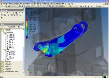
Figure 19 crank equivalent stress cloud
Now let's make a quantitative comparison. We introduce the model into the current market mainstream ANSYS Workbench 10.0, using the principle of force and reaction force to add corresponding constraints and mechanical conditions, analysis. It is found that the analysis of the force trends and results of the two softwares is almost the same. The stress value of AIP11 is relatively conservative. It seems that although AIP11 is a design software, its mechanical analysis capability is still trustworthy.
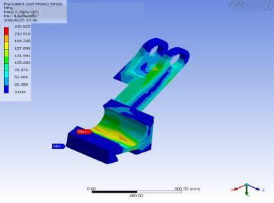
Figure 20 ANSYS Workbench analysis results
Through the actual design problems in the start-stop crank flying shears, I hope that the readers will understand how to use the motion simulation module of AIP11 to understand the whole operation process and solve the problems that plague us in the actual design. AIP11 is a 3D mechanical design software. It provides a reasonable solution from product development to verification and reports related to design analysis, and optimizes the design process under the premise of improving product quality. As a design software, the modification of the model is very simple. With the modification, the required result can be directly analyzed. At the same time, with the design adjustment, the drawing from the part to the assembly and even the production guide will be updated. This is any one. The CAE software is unmatched.
Previous page
Led Christmas Tree Light,Outdoor Waterproof Christmas Lights,Led Christmas Lights For Outdoor,Leds Christmas Tree Lights
Tianjin Jinji Optoelectronic Technology Co., Ltd. , https://www.tjjjgd.com