Additive Manufacturing (AM) offers great freedom to build parts with freeform shapes and complex features, allowing you to make finished products directly from CAD data without the need for costly machining tools. It is very impractical or even impossible to manufacture these complex parts in a traditional way. Parts manufactured by additive manufacturing technology tend to be lighter, more efficient, and perform better.
However, this is not to say that this flexibility allows us to design any shape we want, at least not under cost constraints.
As with any manufacturing process, additive manufacturing technology has its own advantages and limitations. For example, for parts made using laser powder bed melting techniques, if the overhang is designed—that is, where it is to be melt processed at the top of the unmelted powder—it may require a one-time support to be designed to complete the process. These supports increase processing time, consume more material, and require additional post-processing for removal.
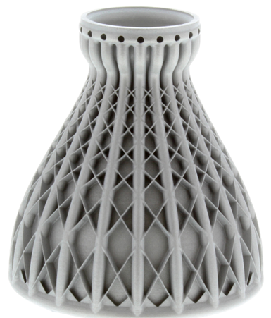
Functionally optimized parts
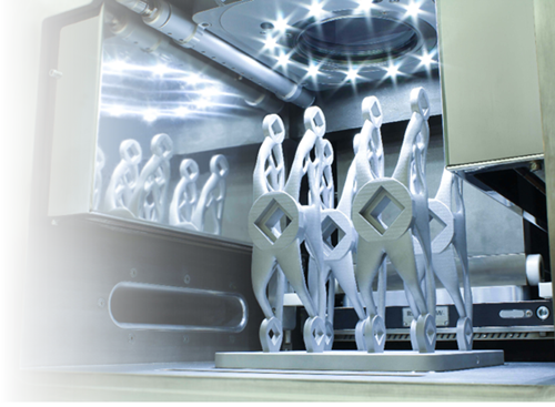
The following figure – Parts that are optimized but not designed for additive manufacturing (AM) may require a large amount of support, resulting in their low manufacturing efficiency.
Therefore, if we intend to use additive manufacturing technology to produce high-performance parts while balancing economics and practicality, then additive manufacturing design (DfAM) becomes even more important. “Does topology optimization really be optimal?†describes the close relationship between functional optimization and process design.
This article describes the key factors that can improve the success rate and productivity of additive manufacturing processes, and explains some of the key guidelines that designers should follow when developing efficient production parts.
Factor 1 - residual stress
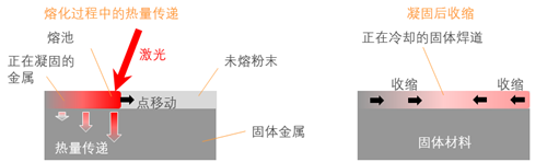
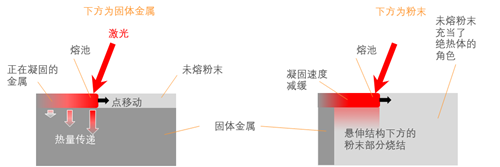
Residual stress is an inevitable result of rapid heating and cooling, which is an inherent characteristic of the laser powder bed melting process. Each new processing layer is constructed by moving a focused laser on a powder bed, melting the top layer of the powder and fusing it with a processing layer below. The heat in the hot melt pool is transferred to the solid metal below, so that the molten metal cools and solidifies. This process is very fast, only a few microseconds.
The new metal layer shrinks when it solidifies and cools on the upper surface of the underlying metal, but due to the limitations of the underlying solid structure, its shrinkage causes shear forces to form between the layers.
Above – The laser melts the metal on top of the solid substrate to form a new weld bead (left). The laser moves along the scan vector and melts the powder, which is then cooled by transferring the heat to the underlying solid metal. After solidification, the cooling metal shrinks and a shear force (right) is formed between the metal layer and the next layer.
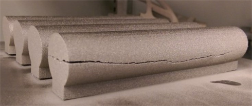
Residual stress is destructive. When we add another working layer on top of one processing layer, the stress builds up and accumulates, which can cause the part to deform, its edges rolled up, and then it may be off the support:
In extreme cases, the stress may exceed the strength of the part, causing destructive cracking of the component or deformation of the processing tray:
These effects are most pronounced in parts with larger cross-sections because such parts tend to have longer welds and shear forces are longer.
Minimize residual stress
One way to solve this problem is to change our scanning strategy and choose a method that best fits the geometry of the part. When we fill the center of the part with a laser trace, the laser is usually moved back and forth, a process called "scanning." The mode we choose affects the length of the scan vector and therefore the level of stress that can accumulate on the part. The strategy of shortening the scan vector will reduce the residual stress generated accordingly:
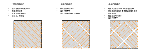
Round-trip scan mode
· Rotate 67° after each layer of scanning
· High processing efficiency
· Residual stress gradually increases
· Suitable for small and thin features
Stripe scan mode
· Uniform distribution of residual stress
· Suitable for large parts
· Processing efficiency is higher than checkerboard scanning mode
Checkerboard scanning mode
· Each layer is divided into several 5x5 mm islands
· Rotate the overall mode and each island area by 67° after each layer scan
· Uniform distribution of residual stress
· Suitable for large parts
Above – Scan strategies and different part types that fit them. The two most common scanning strategies are "roundabout" scanning (also known as raster scanning) for thin-walled parts, and "striped" scanning for parts with thicker sections. The "checkerboard" or "island" scanning strategy is equally effective. Stripe and checkerboard scanning shortens the length of each scan line and reduces the accumulation of residual stress.
We can also rotate the direction of the scan vector as it moves from one processing layer to the next, so that the stresses are not all concentrated on the same plane. Each layer is typically rotated 67 degrees to ensure that the scan direction is completely repeated after processing many layers.
Heating the processing tray is also a method for reducing residual stress, and post-sequencing heat treatment can also reduce accumulated stress.
Residual stress design recommendations
Eliminate residual stress as much as possible by design:
· Avoid large-area uninterrupted melting
· Pay attention to changes in cross section
· Hybrid processing integrates thicker backplane into additive manufacturing parts
· Use thicker processing trays where stress may be higher
· Choose a suitable scanning strategy
Factor 2 - direction
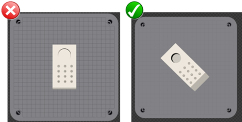
In any lamination manufacturing process, the machine direction is always limited to the Z axis—that is, perpendicular to the processing tray. Please note that the machining direction is not always the general direction. The right direction should be chosen to produce the most stable workpiece with minimal or no support material.
Overhanging part and melting process
In the powder bed processing process, since the shape is constructed in layers, the way in which the layers are related is very important. As each layer melts, it needs the next layer to provide physical support and heat dissipation paths.
When the laser melts the powder layer, if the powder layer is under a solid metal, heat is transferred from the molten pool to the underlying structure, which again melts part of the solid metal and forms a firm weld. As the laser source is removed, the weld pool will also solidify rapidly as heat is effectively transferred out.
If the part has overhangs, at least a portion of the area below the weld pool will be unmelted. The thermal conductivity of these powders is much lower than that of solid metals, so the heat from the bath will remain longer, resulting in more powder sintering around. The result may be that excess material adheres to the underside of the overhanging region, which means that the overhanging structure may exhibit a deformed and rough surface.
  Above – Melting the powder above the solid metal allows for rapid cooling (left). When the powder melting process occurs in the overhanging area, it is required to be cooled for a longer period of time because of the unmelted powder below it, and excess material may adhere to the underside of the part.
Placement direction selection
In general, an overhang structure formed at an angle of less than 45 degrees with the processing tray requires support.
The overhanging surface is referred to as the underlying layer. They usually exhibit a rougher surface than the vertical and upward facing surfaces. This effect is caused by the slow cooling rate of the molten pool resulting in local sintering of the powder below the overhang structure.
It is usually possible to complete the machining of one part in multiple directions. We should choose the direction in which the best part of the part can be supported to minimize the processing cost and reduce the post-processing work.
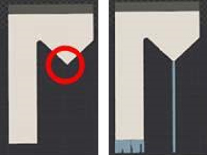
Local minimum
The local minimum is any area on the part that is not connected to the underlying powder melt layer. These areas require the addition of support to secure during processing. If the machining is started without the support structure below, the first machining layer may be displaced when the lower layer is processed by the scraper, resulting in processing failure.
The local minimum may be very noticeable, as shown in the example above. They may also appear at the top of the cross and oblique holes that intersect the edge of the part (as shown in the example below).
Feature placement direction
As mentioned earlier, the surface finish of the lower layer is generally poor. If we are to produce detail features with the best precision, it is best to position these features on the top surface of the part, the upper surface. The detail features embedded in the underlying layer are likely to lose precision.
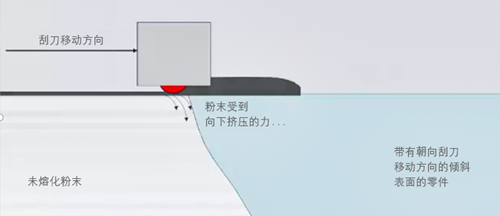
Another issue to consider is the orientation of the part relative to the powder scraper. When a new layer of powder is added, the spatula spreads the powder on the powder bed and the powder is gradually squeezed by the doctor blade to form a new dense layer. When the material is squeezed, a pressure wave is formed on the powder bed. The pressure wave interacts with the surface of the part that is tilted toward the blade direction, squeezing the powder down and squeezing the front edge of the part upwards. This can cause the part to hook onto the scraper, causing the machining to fail. Please note that a flexible blade can reduce this effect.
Above – the interaction of the powder scraper and the bevel of the part.
The support and beveled edges should be placed as far as possible from the direction of the blade. By rotating the part, the pressure wave can now impact the part at an oblique angle, thus reducing the likelihood of part deformation.
If the position cannot be adjusted by rotation, or if the part is rotationally symmetrical, it may be necessary to add support and the affected machined surface may require post-processing.
Place design suggestions
- The processing direction of the parts designed for additive manufacturing should be obvious
- Designers should try to create their own support design
- Processing success is the primary consideration
- Residual stress and surface finish are also important factors in the direction of placement
- The orientation can affect processing time and cost
- Parts with complex geometries may not be easy to place?—it usually requires trade-offs between surface quality, detail, machining time/cost, and support structure.
- Designers must evaluate conflicting factors to determine the direction of placement
Factor 3 - Support
As we discussed earlier, relying on support to overcome the orientation problem is not a good engineering practice. While we may be able to tolerate additional processing time and post-processing costs when manufacturing prototype parts, such waste is unacceptable when mass-producing parts are manufactured. Over-reliance on support indicates that the geometry of the part is “not robust enoughâ€, which has a potential impact on yield.
Support purpose
Although we can design to minimize support, it is sometimes impossible to completely eliminate it. The support has three main functions:
Isolation Material - The support can be used to "fix" the material that is not attached to the previous layer (ie, an overhang structure that forms an angle of less than 45° with the processing tray, or a local minimum point feature). It is best to integrate the support structure into the component design.
Residual Stress - We should design to reduce residual stress during processing, avoid sharp edges, and avoid large areas of processing directly attached to the processing tray. If this is not possible, support can be applied to counteract the stress in the part and prevent the material from falling off the processing tray. This method is not recommended for mass production of workpieces.
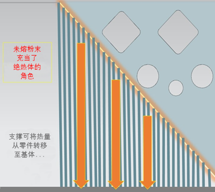
Cooling Channel — Unfused powder is a thermal insulator. The support removes some heat from the lower surface area, which helps to avoid powder burning, excessive melting, deformation and discoloration; it is particularly effective for the lower layer facing the blade direction. The above adverse effects can also be reduced by changing the relative orientation of the scraper to the scraper.
Main support and auxiliary support
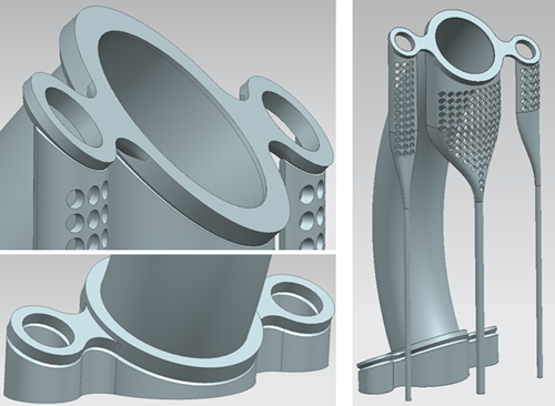
The main support refers to the support that is developed with the components in the CAD environment. It is a one-time structure that will be removed when processing is complete. Auxiliary supports are those that are generated in the processing file processing software.
Main support for exhaust pipes developed in CAD environments
Auxiliary support for exhaust pipes developed in processing file processing software
The main support is characterized by solidity and better controllability. They can be imported into the processing file processing software
(in the form of an STL), or designed with the body of the part. You can also use the full revision control feature
Export them as parameters. Finite element stress analysis can also be performed. In addition, we can design and
Simulate the main support and let it transfer heat in a controlled manner.
Auxiliary support created in the processing file processing software can also be managed by parameters, but lacks traceability
And repeatability. If you change the part design, they may need to be rebuilt.
The hybrid support design takes full advantage of the advantages of CAD design and processing file processing software to achieve the best solution.
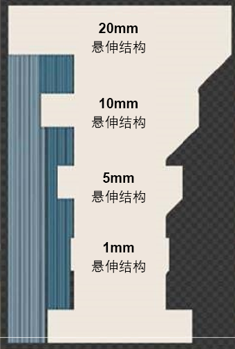
Rounded corners and chamfers
Although a horizontal overhang of 0.3 – 1 mm can be supported by itself, this is not recommended. Exceeding structures over 1 mm must be redesigned or added to support. Fillets and chamfers can be added to the assembly to eliminate the overhang structure (shown below).
The challenge of removing support
Holes and supports in the pipe are difficult to remove and may require subsequent processing. Similarly, too little support can make removal difficult. If the part geometry is more fragile than the support, there is a higher risk of part damage during post-processing.
Horizontal detail - add support or redesign
The lateral holes exposed on the sides of the part may also need to be supported. The minimum size of holes that can be machined on most laser powder bed machines is 0.4 mm.
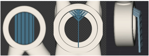
Holes and pipes larger than 10 mm in diameter will need to be supported at their center and should be redesigned. Holes with a diameter between these two dimensions can be machined without the addition of support, but some deformation may occur on the surface of the underlying surface due to the slower cooling rate of the molten pool above the overhang.
Since the roundness of horizontal holes is probably not ideal, a more feasible method is usually to change their shape so that they can support themselves. In some cases, teardrop or diamond shaped holes are acceptable final features. Both profiles are available for fluid passages and provide similar hydraulic performance, but the diamond shaped holes are better able to withstand fluid pressure.
In other cases, post-processing is required if high-precision round holes are required. The diamond hole can be used as a symmetrical guide hole for milling, which is better than a teardrop hole. In many cases, it is probably the most sensible way to machine these holes in the additive manufacturing stage, but to drill holes in the solid structure during the post-processing stage.
- Transform a hole larger than 10 mm into a diamond hole supported by itself
- Use chamfer radius to avoid higher support
- Remove areas with an overhang angle of less than 45° relative to the processing tray
- Rotate the lower layer away from the blade direction
- Processing small features after the additive manufacturing process is completed
- Close to the processing tray to complete part processing while leaving extra machining allowance
- Remove horizontal lower surface area
Factor 4 - Optimization
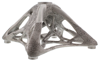
Topology optimization and derivative design are increasingly used to design parts with higher efficiency. The mesh structure also has the advantage of reducing weight. The ability of additive manufacturing technology to produce complex shaped parts makes it the best way to achieve this type of design.
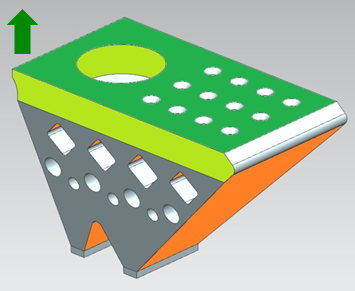
The main purpose of these optimization techniques is to maintain the strength and rigidity of the structure while removing excess material. Optimized parts often present a more complex, organic look. It should be noted that functionally optimized parts may not be suitable for additive manufacturing – especially in terms of the orientation of the machined parts.
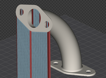
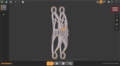
For example, it can be clearly seen that when the part is machined in a horizontal orientation, a lot of support needs to be added to the overhanging areas highlighted in red.
When the part is repositioned in the vertical direction, the area where the support needs to be added will be reduced. Details such as round holes will need to be added or redesigned. Also note that the angle of intersection of the optimized support rod and the fillet radius.
The orientation has been taken into account when re-evaluating the part during the design phase, so it is clear that the part has only one orientation when it is being processed. Now we need to redesign the details of the transverse holes for post-processing:
Optimize design recommendations
- Minimum wall thickness criterion
- Determining the critical surface for processing
- Consider support positioning and removal or redesign so that no support is needed
- Design the part placement direction and modify the details accordingly
- Determine if the required surface finish is achieved
Designers may need to combine various optimization techniques—topology optimization, hollow parts, mesh (if applicable)—to achieve an efficient design. The placement of parts should be another key design driver after applicability, shape and function.
to sum up
Additive manufacturing technology provides great design freedom for the production of high-performance, high-performance parts. However, in order to mass produce parts at the lowest cost and with the least waste, the process characteristics of additive manufacturing must be fully considered.
Incorporating additive manufacturing design (DfAM) ideas into the design process helps maximize processing success and enhances the economics of additive manufacturing processes. Undoubtedly, if designers want to be more competitive, they must not only be more flexible, but also have a deeper understanding of additive manufacturing processes.
For more information, please visit
Automatic Sensor Faucet
Bestware Automatic Sensor Faucet brings the fine design and high technology together in all areas of the product process beyond Pull Out Faucet , Commercial Faucet and Commercial Kitchen Faucet. With extensive range of components, we can offer a large selection of both standard Pre-rinse Faucet and custom Basin Tap units as well as flexible combination. Stainless steel is 100% recyclable and is comprised of over 60% recycled material, Bestware faucets are the perfect solution in the commercial and industry for better water quality and the circumvention of the development of deleterious substances and bacteria. No plating, no oxidizing, no rust, lead free.
Automatic Sensor Faucet,Best Touchless Kitchen Faucet,Touch Activated Kitchen Faucet,Best Touch Kitchen Faucet
Bestware Hardware Production Co., Ltd. , https://www.bestwaremfg.com